Lab 1 - Building Logic Gates
In this lab you will use breadboards to build circuits. You will learn how to use a breadboard, decode resistors, use a logic probe, and build at least one logic gate.
Background Information
Breadboards help you build circuits quickly without soldering; this means you can try things quickly, there are no wasted materials, and luckily no burns or toxic fumes either! Your protoboard has several breadboards mounted on it, with the rightmost column already connected to power and ground. Each breadboard is wired like this:
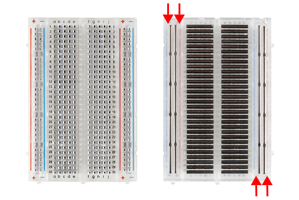
The left and right sides of each board have columns for power and ground, while the remaining pins in the middle are connected in rows. Rows on opposite sides of the “channel” are not connected. This will be useful for using ICs in next week’s lab. To make a connection between two wires, just plug both wires into holes that are in the same row on the same side of the channel. To connect to power or ground just plug the wire into the appropriate column.
It is conventional to use red wire to attach to power (+5V) and black or blue wire to attach to ground. We don’t have many black wires available, but it would still be good to use some dark color for connecting to ground.
Capacitors. A capacitor is a part that does not allow a stable direct current to flow across it, but does allow quick current spikes through. I have placed a capacitor across each of the vertical column pairs described above.
At first glance, it may seem that placing capacitors here is bad news, creating a short-circuit from power to ground. But given the way capacitors work, this short exists only if the board receives a quick power spike—which happens very briefly each time the board is powered on. Their purpose is to protect your circuit from that power spike by letting the spike short-circuit instead. Under normal circumstances (i.e., a stable direct current flow) there is no short-circuit.
DIP switches. For this lab, we will use the dip-switches found near the lower-left of the protoboard. Please keep the black switch to the right of the dip-switches set toward 5V. With this setting, pushing the switch forward makes a connection to 5V, while pushing it backward removes the connection.
Notice that each switch has two connection points (holes) directly above it: they are identical, so you may use either one. To connect the switch to your circuit, all you need to do is run a wire from one of the holes above the switch to the point where you want the switch connected into your circuit. You do not need to connect the switch to 5V (it already is internally in the board), or to ground (you don’t want this).
Resistors. The color bands around the resistors indicate their resistance. A quick Google search on resistors should turn up a nice explanation, and there is a resistance color guide in your toolbox. We have two sizes of resistors in the lab:
- 150Ω: brown-green-brown-silver
- 15KΩ: brown-green-orange-gold
Note that the background color of a resistor is not meaningful.
LEDs. Since these are diodes, they must be inserted in your circuit with the correct orientation. Connect the longer lead toward +5V and the shorter lead toward ground.
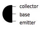
Transistors. The leads on a transistor are arranged like this:
Wires. A couple of tips about choosing wires for your ciruit. Using short wires is good: if your wires are longer than necessary, you will find that the excess gets in the way. Keeping the wires sorted by size will help you and others using your station find the ones you need next time.
Logic probe. The protoboard at your station includes eight logic indicators. You can use these to test whether a given point in the circuit is at high or low voltage. Please keep the lower switch set for TTL logic. Start out with the upper switch set to +5V.
To use the probe, connect a wire to one of the holes in the logic probe’s mini-breadboard. Touch the other end of this wire anywhere in your circuit to see if that point is at high, low, or indeterminate voltage. If you are using the logic probe with a loaded circuit (one with an LED on it, for example) the voltage may not be high enough to trigger the high level (but still too high to be low voltage).
Try not to make more than one connection with the probe at a time (i.e., try not to create a short-circuit through the probe).
Exercise 0
Is your logic probe set to TTL and +5V? Are your logic switches set to +5V? Remember to hook LEDs up through a resistor, or they will burn out!
Exercise 1
What do you expect the voltage to be at points A and B? Build this circuit on your protoboard. Remember that only the connections in the circuit matter, not the layout. You probably will not be able to replicate the layout from this diagram.
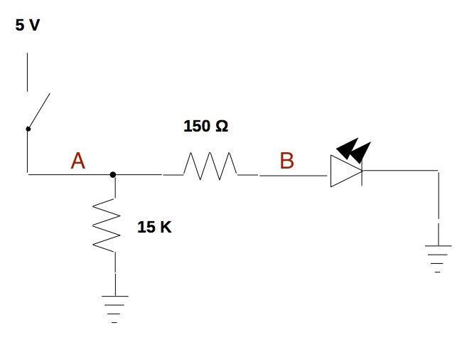
Connect a wire to one of the logic indicators and test the voltage at each point. Were your predictions accurate?
If nothing lights up, try switching to +V mode and turning the +V dial down to zero. This will cause the high voltage light to turn on at less than +5V volts. Why would a point on the circuit trigger high voltage, but not +5V?
Show me your circuit before moving on to the next exercise.
Exercise 2
What do you expect the voltage to be at points A, B, and C when the switch is on? What about when the switch is off? What kind of logic gate do you think this is? Make a note of your predictions before building the circuit.
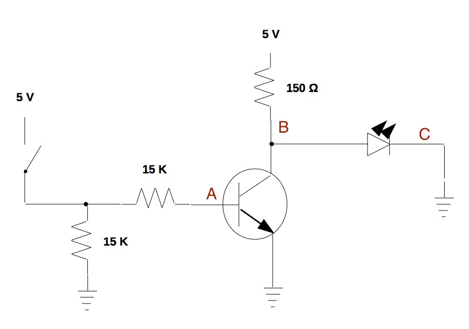
Use the logic probe to measure the logic level at each labeled point and compare these to your predictions. Could you tell which kind of circuit this was? How did you know, or how will you remember in the future?
Before you move on to the next exercise, please show me your circuit.
Exercise 3
If you have time, build an AND or OR gate on your breadboard using two DIP switches to provide inputs and an LED to show the output. Make sure you work with your partner to diagram out the gate first!
If you get a more complex logic gate working, please show me!