Lab 4 - Latches and Flip-Flops
In this lab, you will build a working D-type flip-flop.
Step 1: Build an S–R latch
Build an S–R latch on yor protoboard using the following circuit diagram:
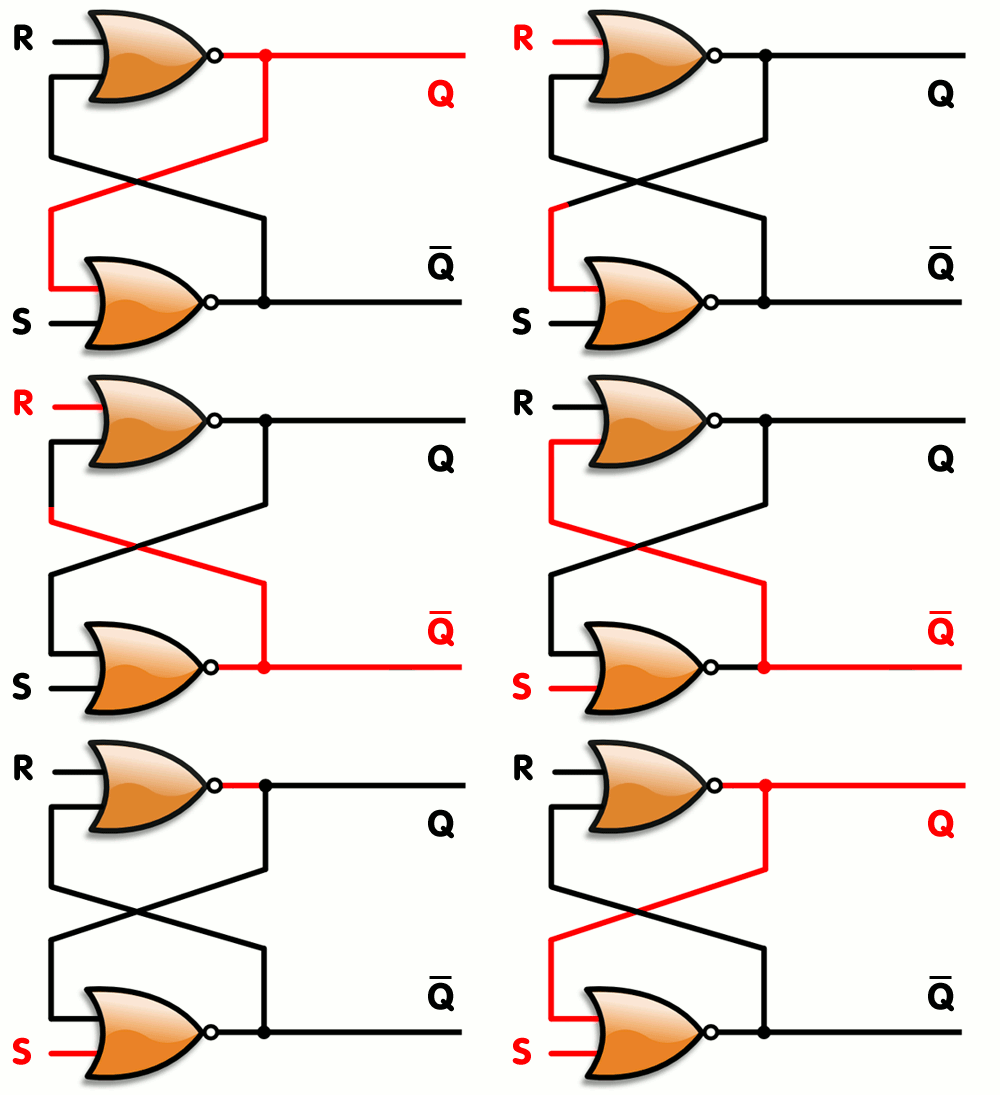
Image from Wikipedia
Test your S–R latch. How do you know it is storing a value?
Step 2: Build a D latch
Add the necessary gates to turn your S–R latch into a D latch. Recall that a D latch has two inputs and two outputs:
- input
- The data value that should be stored in the latch
- input
- The clock input. When this pin is high, the value on is stored in the latch. If is low, then the stored value should not change. Note that this input is sometimes called , for “enable.”
- output
- The stored value in the latch
- output
- The inverse of the stored value
Test your D latch to verify that it stores the correct value, and only updates the stored value when the clock input is high.
Step 3: Drive your D latch with a clock
Connect the input of your D latch to the clock signal on the left side of your protoboard. You should hook a logic indicator light up to the clock input so you can monitor it. Set your clock to a low frequency (Hz, not KHz, and 1, not 10 or 100).
With the clock set slow enough, you should be able to watch the value on update the latch state only when the clock is high.
What happens when you change while is still high?
Step 4: Build a D flip-flop
Build a second D latch and connect it to your first D latch to build an edge-triggered flip-flop. The following figure shows a D flip-flop that stores an input value on the clock’s falling edge. How would you build a flip-flop that stores on the rising edge instead?
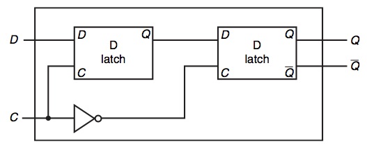
Image from Patterson & Hennessy
Citations
Acknowledgment: This lab is adapted from a lab introduced to Grinnell College by Marge Coahran and updated by Janet Davis.
 This work is licensed under a Creative Commons Attribution-Noncommercial-Share Alike 3.0 United States License.