Lab: Build an ALU
- Assigned:
- Wednesday, Sep 13, 2017
- Due:
- Monday, Sep 18, 2017 (by 5pm)
- Summary:
- For this lab you will implement the major pieces of a 1-bit ALU. This requires that you build both an adder and multiplexor on your protoboard and connect them together so be careful with your layout.
- Collaboration:
- Work with your assigned partner for this lab. You may use your classmates as a resource, but please cite them. Sharing of complete or nearly-complete answers is not permitted. If you do not know whether it is acceptable use a specific resource you should ask.
- Submitting:
- After completing each exercise, show your completed circuit to the instructor or a course mentor. If you are unable to complete the lab during class time, schedule a time during office hours to demonstrate each of your circuits.
Groups
- Esther, Dennis, and Hoang
- Zachary and Paps
- Nick and Reilly
- Rojina and Greyson
- Kathryn and Mari
- Nripesh and Clara
- Faizaan and Andrew
- Aditi and An
- Bazil and Gemma
- Jimin and Ryan
- Matt and Lex
- Prabir and John
Build a one-bit full adder
Using the logic diagram below, build a full adder on your protoboard. Plan carefully; you will need to leave space to build a one bit multiplexor on your board, but you can
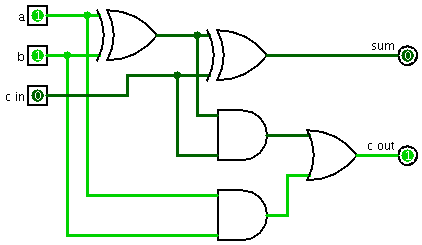
Write a truth table for the full adder and test it to verify that your circuit is working correctly.
Build a two-bit decoder
Use four AND gates and two NOT gates to build a two bit decoder. One way to think of a decoder is a binary to unary converter: the two input bits specify a binary number. That number determines which output line is turned on, while the rest are off.
Don’t disassemble your decoder—you will use it in the next step to build a four input multiplexer.
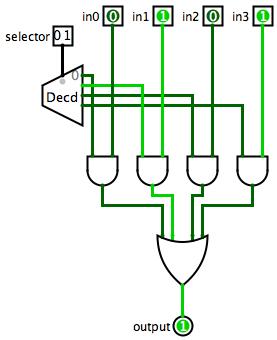
Build a four-input multiplexor
You can turn a two bit decoder into a four input multiplexer with four AND gates and three OR gates. Use the two inputs to your decoder as the selector lines. Use four logic switches as your multiplexer input (for now). Connect each input to an AND gate, along with one of the decoder outputs. Connect all the AND gate outputs to a four-input OR gate, which you will have to construct from two-input OR gates. The logisim circuit below shows this circuit, using your existing decoder:
Finish your ALU
Now that you have a one-bit adder and a four-input multiplexor, complete your ALU with AND and OR gates. You will use the selector in your multiplexor to choose between addition (selector at 00), logical AND (selector at 01), and logical OR (selector at 10).
Once you have completed your ALU, demonstrate the ALU for Charlie or a class mentor. If you run out of time to finish your circuit during lab time, you may complete the circuit on your own time and demonstrate the complete implementation during office hours.