Lab: Meet the PIC32
- Assigned:
- Wednesday, Sep 27, 2017
- Due:
- Monday, Oct 2, 2017
- Collaboration:
- Work with your assigned partner for this lab. You may use your classmates as a resource, but please cite them. Sharing of complete or nearly-complete answers is not permitted. If you do not know whether it is acceptable use a specific resource you should ask.
Overview
Starting in this week’s lab, we will be working with the PIC32 processor and the Microstick development board. The PIC32 is a popular line of microcontrollers that implements the 32 bit version of the MIPS instruction set, the same instruction set covered in our textbook. In this lab we will learn to use the MPLAB IDE to assemble code and download it to the Microstick, how to step through a program’s execution using the MPLAB Debugger, and how to use the PIC32’s port I/O to interact with circuits on your protoboard.
Groups
- Matt and Paps
- An and Clara
- Rojina and Ryan
- Faizaan and Prabir
- Greyson and Nripesh
- Gemma and Nick
- Andrew and Dennis
- Zachary and Kathryn
- Lex and Reilly
- John and Aditi
- Mari and Bazil
- Jimin and Hoang
Background
The specific processor we are using is the PIC32 MX110F016B, along with the Microstick II development board. The Microstick II, with a processor installed, looks like this:
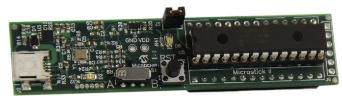
The microprocessor is the large component on the right. While there are many standard layouts (or “packages”) used for microprocessors, observe that the processor shown is in an SPDIP package, with two parallel rows of pins, similar to the TTL logic chips you have already used in lab. The physical form of the Microstick II development board means it can be easily plugged into our protobards and connected to other electronic components.
The devices used in this lab are based on CMOS technology, and as such, they are more sensitive to small static shocks than are the TTL logic chips we used previously. Even a shock that you don’t feel can damage the chip, so please avoid touching the microprocessor with your fingers. Please also be careful not to drop anything metal (e.g., wires, rings, or paperclips) onto the development board as this could also damage the board or the chip by causing a short circuit.
Resources
As you work through this lab, you may want to refer to the following references:
- Patterson & Hennessy, Chapter 2
- MIPS32 Reference Card
- MPLAB X IDE User’s Guide
- PIC32MX1XX/2XX Family Data Sheet
- PIC32 Family Reference Manual, Sect. 12 I/O Ports
Part A: Getting Started
When you are ready to begin your lab, go to the equipment room and grab a Microstick II (in a small red and black box) and a protoboard. You will not need the protoboard’s power cable today; all the power for our circuit will come from the Microstick.
Microstick II Components
Take a good look at the Microstick II development board. Identify the PIC32 microprocessor. Moving upward, you should also see a round button, which is the reset (or “RST”) button, which is used to restart the microprocessor from its initial state. The PIC32 will begin executing whatever program it last received as soon as it gets power. Pressing the RST button will restart the program. Above this is a switch with positions labeled A and B. For our PIC32, we want the switch in position A (some other PIC32 processors use different pins to connect to the computer, and the Microstick supports both using this switch). Above the toggle switch is a small green LED which indicates whether the board has power. Above the LED is a USB connector, which is used to power, program, and debug the board.
Setting Up
Plug the microstick into the protoboard so it crosses a gap in the breadboard; you do not want to connect the two columns of pins. To make sure pin positions match the documentation, orient your Microstick so the A/B switch and RST button are on the left, and the USB cable is at the top (furthest away from you). Once the Microstick is in place, use the USB cable in your box to connect the board to your computer. Verify that the power LED is lit.
Start MPLAB
Log in to your MathLAN workstation if you haven’t already. Open a terminal and run the following command to start the IDE we will use to program the PIC32:
/home/curtsinger/bin/mplab_ide &
Make a Project
Once MPLAB has started up, follow these steps to create a project:
- Under the File menu, select New Project.
- Select the “MicrochiP Embedded, Standalone Project” type and click Next.
- To select our devices, choose the family of 32-bit MCUs (PIC32) from the first dropdown.
- Next, select “PIC32MX110F016B” from the second menu and click Next.
- On the next screen, look under the “Microchip Starter Kits” heading and select the Microstick II option and click Next.
- On the next screen, select the XC32 compiler and click Next.
- Enter “Add” as the project name and accept the default settings for all the other options. Click Finish to create the project.
Create an Assembly Source File
Next, we will add a source file to the project.
This file will use the .s extension, which tells MPLAB to build it using the MIPS assembler.
Please pay close attention to file extensions in MPLAB!
- Go to the File menu and select New File.
- Select the “Other” category, and choose “Empty File”. Hit Next.
- On the next screen, give the file the name
add.sand hit Finish.
The add.s file should appear under source files in your IDE.
Double click the file to open it, and paste in the following code:
# add.s
# Written by Jan Erik Larsson, 27 October 1998
# Adapted by Janet Davis, 6 October 2013
# Modified by Charlie Curtsinger, September 2017

  .set noreorder    # Avoid reordering instructions
  .text             # Start generating instructions
  .globl main       # The main label should be globally visible
  .ent main         # The label marks an entry point

main:
  li  $s0, 0x1      # Load the value 1 into $s0
  li  $s1, 0x1      # Load the value 1 into $s1
  add $s2, $s0, $s1 # Add the values
  nop               # Do nothing
.end main           # Marks the end of the program
The first four lines of this programare directives that tell how the program should be translated by the assembly.
The three lines starting with the label main produce actual machine instructions. You should be able to explain what these instructions mean and what the program does when executed.
The li pseudo-instruction takes an immediate value and loads it into a register.
Before comverting to machine code, li is translated to the actual instruction addiu $s0, $zero, 0x1.
Comments are preceded by #.
All the programs that you write for this course should include informative comments.
Try to be consistent with your use of whitespace.
Run a Simple Program
To build and run this program on the PIC32, click the big green arrow button at the top of the IDE. This will compile the program, and if it compiles without errors, it will program the device and start executing the code.
If this is the first time the microprocessor has been used, the IDE will go through several steps to not only download your code to the device, but also to download appropriate firmware. This process is complete when you see the text “Programming/Verify complete”. If you don’t see this text, ask for help.
There are a few warnings that could pop up at this stage. You can ignore warnings about serial numbers and device IDs not matching, but please ask for help if you receive any warnings about programming or communicating with the Microstick.
Assuming the programming finishes successfully, the microprocessor is now running your code. Unfortunately, our simple addition program has no visible effects. We will get to blinking, but first we will use the Microstick II’s onboard debugger to step through the program as it executes.
Part B: Using the MPLAB Debugger
We will use the debugger to step through our program line by line and view the corresponding changes to the values stored in the microprocessor’s general purpose registers.
Set a Breakpoint
Click the line number next to the first li instruction to set a breakpoint. A breakpoint tells the debugger to stop before executing the indicated instruction.
View the Contents of Registers
In addition to setting breakpoints (which should be familiar from GDB), the MPLAB debugger allows us to view the values in each MIPS register. Follow these steps to set this up:
- Under the Window menu, choose PIC Memory Views, then CPU Registers. You will see a new tab pop up showing the CPU Registers.
- Click on the heading of the leftmost column to sort the registers by Address. At the top, you will see a number of special purpose registers used to manage the processor’s current configuration and status, starting with
BadVAddr. Note that these registers do not have addresses; they are not accessible through typical assembly language instructions. - Scroll down until you find the general purpose registers, starting with
r00, otherwise known aszero. Keep scrolling until you findr16,r17, andr18, otherwise known ass0,s1, ands2. - Leave this view up while you continue this section of the lab.
Start Debugging
Under the “Debug” menu, click “Debug Main Project”. This will rebuild your program for use with the debugger and also configure the microprocessor appropriately. You will probably be asked whether you want to disable the “Watchdog Timer” during this processor; you can select “Yes”.
At the end of the build process, you should see the words “Target Halted,” which indicates that the microprocessor is halted and waiting for you to tell it what to do next. You should also see that the first line of your program is highlighted in green, and there is a green arrow over the red breakpoint square to the left of the program. The green arrow and highlight indicate the instruction that will be executed next.
Single Stepping
Click on the CPU Registers tab to go back to inspecting the values stored in the registers. Make sure you can see the registers used by your program. This view, along with the source view, will show you the effect of each instruction you execute in debug mode.
Step into the current instruction by clicking the toolbar button with an orange arrow pointing down, or by touching the F7 key.
You should see the green highlight move down to the next line of your program.
MPLAB will also show you the updated value in register $s0.
Step through the next two instructions and make sure you can see updates to the registers.
Now, the nop instruction should be highlighted. What do you think will happen when you reach the end of the program? Step once more and find out.
Click the stop button to halt the program execution and exit the debugger.
More Debugging
Add a jump instruction that will cause an endless loop. After the add instruction, add the instruction j main to jump back to the first instruction.
Leave the nop as the last instruction (remember that jump instructions take two cycles to execute on the PIC32; therefore we use the nop to fill in the extra cycle.)
Re-assemble and debug your program.
What happens when you step through the program line by line?
How can you stop it?
Modification #1
Modify the program so that it does something a bit more interesting. Instead of performing the same addition over and over, have the program continually add 1 to the same register, so that it counts up as the program executes. Debug your program and verify that the value of the register increases on each pass through the loop. After how many loop iterations will overflow occur?
After completing this modification to the original program, have the instructor or a mentor sign off on your work. Don’t forget to write comments in your assembly!
Modification #2
Modify your program so that it counts by 2, 5, or another small integer, instead of counting by 1.
After completing this modification to the original program, have the instructor or a mentor sign off on your work. Don’t forget to write comments in your assembly!
Part C: Getting Started with Port I/O
The first program uses only internal registers. However, the second program will take advantage of the PIC32’s input/output pins to turn an LED on and off. Pay close attention to the instructions for this part; there are quite a few details that you have to get right for the code to work!
Setting Up
Create a new project named blinkonce using the same process as before.
As you finish creating the project, set it as the main project.
You can do this in the new project dialog, or by right-clicking on the project in the IDE.
Create a new source file named blinkonce.S.
Make sure you use the suffix .S and not .s.
This is required because our second program will use named constants.
These constants are replaced with actual values using the C preprocessor, and only .S files are run through the C preprocessor.
If you use a .s extension on accident you will have to delete the file and create a new one;
MPLAB does not allow you to change the extension of an existing file.
Starter Code
Paste the following code into blinkonce.S:
# blinkonce.S
# Written by Janet Davis, 6 October 2013

  .set noreorder  # Avoid reordering instructions
  .text           # Start generating instructions
  .globl main     # The label should be globally known
  .ent main       # The label marks an entry point

#define ON  0x1
#define OFF 0x0

main:
  la  $s0, TRISA  # Load the address mapped to the TRISA control register
  li  $t0, 0
  sw  $t0, 0($s0) # Store the value 0 to all bits of the TRISA register,
                  # setting all bits of Port A as output

  la  $s0, LATA   # Load the address mapped to the LATA control register

  li  $t0, ON
  sw  $t0, 0($s0) # Write to LATA, turning the LED on

  li  $t0, OFF
  sw  $t0, 0($s0) # Write to LATA, turning the LED off

  nop             # Do nothing
  .end main       # Marks the end of the program
The la pseudo-instruction is similar to the li pseudo-instruction, but loads a memory address (known at link time) rather than a constant. See John Loomis’s notes on load immediate, add/subtract, and logic operations for further discussion and examples.
This program will work because the Microstick II connects the first pin of Port A—one of two one-byte “ports”, a sequence of 8 pins—to an LED built into the board. Interacting with the port is a bit strange; there are two main steps:
- The constant
TRISAis the location of a memory-mapped register (just a special location in memory) that controls whether the Port A pins should act as inputs (1) or outputs (0). By writing all zeros to this location, we have set up eight output pins. This only has to happen once at startup; we can turn the pins on and off all we like once they are set up as outputs. - The
LATAconstnat is the location of another memory-mapped register. With this location, writing a 1 to any of the bits will turn on the corresponding pin, and writing a 0 will turn the pin off. You can see the program above storesONto this location to turn on the first bit, and storesOFFto turn the first bit off.
Debug the Program
Debug the program, executing it step by step. Investigate what happens to the register values. (You may need to make the status pane a bit bigger to see all the registers at once.) Also observe that the Microstick II’s onboard user LED, which is red, blinks on and then off as you single-step through the code.
In the CPU Memory pane, choose to inspect the Peripheral Memory instead of the CPU Registers. Sort by name and find the LATA register. What is the address corresponding to LATA? What value is stored there? Step through your program again and see how the value changes.
Use an External LED
Let’s try connecting an external LED to pin 0 of Port A.
- In the PIC32MX1XX/2XX Family Data Sheet, find the pin diagram for the 28-pin SPDIP package on page 4. Focus at the diagram on the top of the page, which is for the PIC32MX1XX product series.
In the pin diagram, find pins labeled for pin 0 of Port A (RA0) and for ground (VSS). Make note of the pin numbers.
Grab a green LED and a 150Ω resistor. Build a circuit connecting the power lead of the LED to RA0, the ground lead of the LED to the resistor, and the resistor to VSS.
Use the debugger to step through your program again. Verify that the green LED turns on and then off again, along with the red LED on the Microstick II, as you step through the appropriate instructions.
Modification #1
Use your MIPS assembly skills to add a loop to this program so it will repeatedly turn the LED on and off as you single-step through it with the debugger. Once your modified program works, have the instructor or a mentor sign off on your code. Don’t forget to write detailed comments in your assembly!
Acknowledgements
This lab was developed by Janet Davis, and inspired by exercises written by Marge Coahran and by Mats Brorsson and Jan Eric Larsson.
 This work is licensed under a Creative Commons Attribution-Noncommercial-Share Alike 3.0 United States License.