HW 1 - Circuits and Gates
Due at 10:30pm on Monday, September 7, 2015
- Posted
- Tuesday, September 1st
- Note
- Circuit and logic gate diagrams may be neatly hand drawn and scanned/photographed. Everything else should be typeset.
Problem 1
Suppose you tried to construct the following circuit in lab, but you find that the LED does not light regardless of how the switch is set.
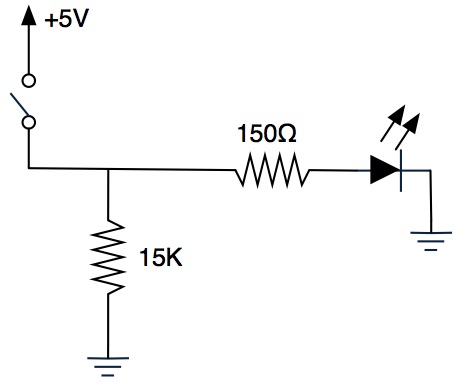
Suggest at least four potential problems you should check for.
Problem 2
You recently learned how to build a two-input OR gate with transistors. A three-input OR gate is asserted (1) when any of the three inputs are asserted and deasserted (0) when all three inputs are deasserted.
- Write the truth table for a three-input OR gate.
- Draw a circuit diagram using transistors to build a three-input OR gate.
Problem 3
Consider the following circuit.
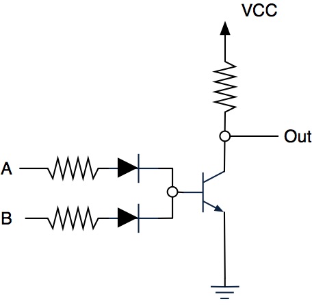
- Explain the value of the voltage at
Outfor all settings (VCCorGND) ofAandB. - Explain what type of logic gate this circuit represents.
Problem 4
Consider the following truth table.
| A | B | C |
|---|---|---|
| 0 | 0 | 1 |
| 0 | 1 | 0 |
| 1 | 0 | 0 |
| 1 | 1 | 1 |
- Draw a circuit diagram using transistors (either NPN or PNP as appropriate) that implements this function.
- Briefly explain how/why your circuit handles each of the four possible settings of
AandB.
Problem 5
Consider the boolean function
- Draw a logic gate diagram for using only NOT gates and two-input AND and OR gates.
- Write the truth table for .
- Explain the gate delay for your diagram of .
Acknowledgments
Problems 1, 2, and 5 are by Janet Davis. Additional problems and revisions by Jerod Weinman. (Used by permission.)